| For kite-energy, think "tether" replacing motor or engine of powered autogyro to have "gyrokite." [See index Gyrokites ] | |||||||||||||||||||||||||||||||||||||||||||||||||||||||||||||||||
|
http://www.w-p.dds.nl/bookaut/
No one author. The essay is freeware and open for the world to send in edits.
The work is NOT COPYRIGHTED. Send notes to indicted people. The
statements very well could be improved; corrections may need to be made. Help
from anyone is invited.
Discuss the essay and places notes to improve the essay by posting in the topic thread: AirborneWindEnergy/conversations/messages/11901 What is an Autogyro?
An autogyro is an aircraft that uses a freely rotating rotor as a wing.
Because the rotor rotates freely, it does not apply an axis torque on the
fuselage and there is therefore no reason for a tail rotor. Furthermore, the
rotor is not attached to the engine, so a propulsion in the form of a
propeller or jet engine is needed for powered flight. Or a tether needed
to have a gyrokite in which case wind is then needed; but manned kiting a
gyrokite as very special safety cautions because of gust events; have low
winds and a moving vehicle anchor so the apparent wind is smoother and more
predictable; avoid thermic conditions. Get training from experienced
gyrokiting masters. Autogyros are also called "windmill planes". This name describes the autogyro nicely: it is nothing more than a flying windmill. The only difference between an autogyro rotor and a normal windmill is the fact that an autogyro rotor is designed to generate lift instead of shaft power. |
|||||||||||||||||||||||||||||||||||||||||||||||||||||||||||||||||
The Book of the Autogyropreface
This book is about autogiros, autogyros, gyroplanes, gyros, gyrocopters,
windmill planes or whatever you may call them. Most people call them
gyroplanes nowadays, but the other names can and will be
used throughout this book as well.
This book is written by lots of people and will probably never be finished, because it was written by you, the internet user. It combines many items from newsgroups and other homepages and personal contributions. What is written in this book is not necessarily correct or true, but I have checked and recalculated the data where possible. Some parts may be meant to start a discussion about the subject. Nobody will take any responsibility regarding the contents of this book NOT© This book is not copyrighted and may be printed and copied, as long as nothing is charged for the copies and/or printouts. In other words: This book is freeware. All contributions to this book will be treated as freeware as well.
If you want to contribute something to this book, you can send your
contribution to:
This online book is meant to be viewed with all browsers, such as Lynx, Netscape and MS-IE. If you have trouble viewing it with your browser, please let me know. Left and Right
If you encounter any directions in the text, please imagine that you are the
pilot of the autogyro. Every direction is seen from the pilot's viewpoint,
unless it is clearly stated otherwise. So "left" is always "portside", and
"right" is always "starboard".
|
|
||||||||||||||||||||||||||||||||||||||||||||||||||||||||||||||||
|
Most autogyros (there are always exceptions)
consist of the following "body-parts":
The rotor
No exception to that. Every autogyro has a
rotor that keeps it in the air. The rotor has two or more blades, which are
attached to the axis with several hinges. These hinges prevent the aerodynamic
moments that result from the forces on the blades to be transferred to the
axis and the fuselage. To put it more clearly: The hinges form the difference
between a rotorcraft rotor and a boomerang. These hinges are so important that the
invention of the hinges in rotors (by Juan de la Cierva) can be called the
invention of all rotorcraft.
Flapping HingesThe most important of these hinges is
the flapping hinge. Flapping
hinges allow the rotor blades to move up and down. As the advancing blade has
more airspeed than the retreating blade, the advancing blade will produce more
lift. Due to the gyroscopic effect of the rotor, the front blade
will go up. (Rotating things tend to react to forces a quarter of a cycle
later...) The lead-lag
hinge allows a blade to "run
in" or "get behind" with respect to other blades. This is mainly to compensate
for the extra rotational speed that comes with blade flapping. It also
compensates for differences in blade drag in various moments of one cycle. Feathering Hinges The featering
hinge makes it possible to
change the pitch setting of a rotor blade. It is perfectly possible to build
an autogyro rotor without feathering hinges, but you will need the feathering
hinges during the spin-up if you do a jump start. It must be noted that present day autogyros and helicopters are fitted with far less hinges than described above. This is because the effect of the hinges can be achieved with other rotor constructions:
The (always two-bladed) teetering rotor with direct axis control is a special case. It uses the fact opposing blades have opposing movements. It has therefore one central flapping hinge for the beam that forms the two blades. It uses the rotor shaft as a central lead-lag hinge. Feathering hinges are usually omitted on light and ultra-light autogyros.
The mast
Well, the rotor should be attached to
something. It is funny to see that rotors with direct axis control are usually
attached to a mast. For autogyros with articulated rotors, the rotor is
generally attached to the cabin roof.
This has everything to do with weight. For ultralight autogyros, a load-bearing cabin would be far too heavy and the loads are therefore carried by a frame of beams. The vertical beam is called the mast, and carries the loads from the engine, the seats and the rotor. For heavier types, a load-bearing cabin is a better alternative. But that's not all. Most light autogyros are equipped with unarticulated rotors. These unarticulated rotors are always two-bladed, and two-blade rotors suffer from large periodic drag difference. This can be explained as follows: if one blade is pointing right and the other one left, the rotor catches more wind than in the situation that one blade is pointing forward and the other one aft. The flexibility of the mast allows the rotor to shift back and forth somewhat, eliminating large bending moments in the blade roots. Rotors with more than two blades always have lead-lag hinges to prevent those bending moments and also suffer less from periodic drag difference. The fuselage
The fuselage is only meant to keep everything
else together. Sometimes it has a nice shape to keep the drag at a moderate
value and a windscreen to keep the pilot out of the free airstream.
In fast autogyros, keeping the drag at a moderate value is not only a matter of performance, but also a matter of control. With increasing airspeed, the fuselage drag increases more than the rotor drag and therefore the "center of drag" moves downward as you fly faster. To compensate for this effect, one Wallis WA-116 was fitted with canards. The tail group
The tail group will keep the fuselage
going in the right direction. In most cases, it consists of a horizontal and a
vertical surface
Vertical SurfacesAll autogyros need some vertical tail surface to stabilize
the fuselage. Pusher type autogyros will need a rudder too, to compensate for
some yawing effects. Especially when you make a landing flare, you are
reminded of the fact that your propellor (which for some reasons was always
free of hinges) is acting as a gyro. A gyro wants to do everything a quarter
of a cycle later, so an increase in banking angle of the propeller will result
in a yawing force on the fuselage. As the largest change in banking angle is
likely to occur in a landing, you will be grateful if the designer of your
autogyro has mounted the rudder in the propeller slipstream. Horizontal SurfacesHorizontal surfaces are not strictly necessary, because the gravitation will keep the fuselage hanging beneath the rotor. However, this is only true if other forces (except for the lift) are small with respect to the weight: that is when you are flying in a steady, slow flight.If you are flying fast, the drag and the propulsion force can be large enough to bring the possibility of pilot induced oscilation (See the Possible Problems chapter) Notice that the tail group stabilises the fuselage only. The rotor itself is quite stable and is not in any way stabilised (because of the hinges in the rotor) by the tail group. The undercarriage
You may have wondered why the wheels of an
autogyro are so far apart. That is because the undercarriage are not "just
some wheels to stand on". The wheels also prevent the autogyro from falling
over in case of rotor eccentricities. The undercarriage is always flexible to
some amount, and this flexibility can interact with the rotor flexibility,
which is built-in in the form of hinges (see Ground
Resonance in
the Possible Problems chapter).
In the case of an autogyro with a jump starter, it is also the anti-torque device and must have a firm grip on the ground. It helps if the rotor pushes the autogyro downward during the spin-up phase of a jump start. The propulsion [[Replace motors with kite tether for towing/kiting when considering kite-energy systems.]]
Autogyros with jet engines have existed, but
most autogyros are simply too small to make a jet engine effective. So you
will generally find autogyros with propellor engines, and most of them are
pushers.
During the start, the engine can drive the rotor on most autogyros. This "pre-spin device" is either called a prerotator or a jumpstarter, depending of the type of start it was designed for. A prerotator just helps the rotor spin up before the actual take-off run. A prerotator does not give the rotor enough energy for take off, but just shortens the take-off run. A jumpstarter is meant to give the rotor enough energy for a vertical start, usually 1 1/2 times the normal flight rpm. As soon as the rotor is uncoupled from the engine, the pilot pulls the collective (or this is done automatically) and the autogyro "jumps" in the air. Once airborne, the pilot should gain forward speed immediately. |
+
+
+
+
+ +
+
|
||||||||||||||||||||||||||||||||||||||||||||||||||||||||||||||||
How to Behave
|
|||||||||||||||||||||||||||||||||||||||||||||||||||||||||||||||||
![[Download crick.gif (11K)]](http://www.w-p.dds.nl/bookaut/crick.gif)


![[Download teetrot.jpg (6K)]](http://www.w-p.dds.nl/bookaut/teetrot.jpg)
| Thou shalt react a quarter of a cycle later. |
An example. If you look at the picture, you can see me holding a diabolo.
Suppose I move my right hand forward (towards you) and my left hand backward
(away from you). If the diabolo is not spinning, it will turn left (yawing
movement). However, if the diabolo is spinning, it will turn either forward or
backward (banking movement). If the direction of rotation is such that the
right-hand side is moving up, it will rotate forward.
In other words: If I give it a turn about a vertical axis, it will respond by
turning about a horizontal axis.
This phenomenon is also visible in autogyro rotors: clearly the advancing blade will get the most lift and will therefore be pushed up. As a reaction it will be the front blade (a quarter of a cycle later) that moves up.
Let's look at a frisbee. If you throw it without giving it a spin, it will
increase its angle of attack until it whirls out of the air. This will happen
just within a few meters.
Now throw it again, but give it a spin while you are throwing it. Now it can
fly easily over a hundred meters. It will turn slightly away from the thowing-hand
if you have launched it horizontally. This brings us to the second law of
rotating things:
The faster you spin, the less you should bother to react to external torques
that are not acting about the rotating axis.
In other words:
| The faster you rotate, the more stable you are. |
In an autogyro rotor, rotational speed is needed to keep the blade flapping at a normal level. If, for whatever reasons, the rotor turns at a low speed, the blades can hit the stops too hard due to excessive blade flapping. This is one of the reasons why the rotor must be secured when the autogyro is parked outside.
You might be more familiar with a boomerang. Let's use the aforementioned
laws to describe the path of a boomerang.
Using the second law it will show a slow change of course.
Using the first law, we come to a complicated orbit. You launch a boomerang
like this: Take the boomerang in your right hand, by the lower blade. Hold the
boomerang such that it will generate lift towards the left. Throw it away with
a good spin.
The upper blade will
now generate the most lift, causing the front
blade to be pushed to the left
(first law). The boomerang turns left and will keep on turning left until it
gets back to you or runs into something. As a secondary effect, the front
blade is so wide that it will
catch wind, causing the lower
blade to be pushed a little to
the left as well, so that the boomerang "flattens out": it will fly in a more
horizontal way when it gets back to you.
With some boomerangs (I've seen one that did it in my life) you can see
another phenomenon: it catches up more rotational speed just after you've let
it go. This is something familiar. It's called autorotation.
You can now understand why the hinges in rotors are so important. Before Juan
de la Cierva built his autogiros, he built models first.
These models flew relatively well, but when he built the first real-size
autogiros, these aircraft rolled over to the size when taking off. In fact,
the rotors still behaved like boomerangs. It was only when he realised that
his models could fly because of the flexibility of their blades, when Juan de
Cierva decided to use flapping hinges.
 |
Forces on the Autogyro
In Flight
Lift can be
generated by a rotor, the fuselage and wings. Wings are seldom used anymore,
except for an interesting project to build an economical jump-start airplane
(see the web page of Cartercopters)
As you see in the picture, the lift is not in line with the weight, and for a
climbing autogyro the combination of lift and weight is slowing down the
aircraft. If the aircraft was descending, this combination would be speeding
up the aircraft (as you all know from gliders).
Where there is lift, there is Drag (symbol: D ). Drag is not something bad, it is just something you should live with. Drag keeps you rotor rpm at a nice value and in general it puts reasonable limits to everything. Drag has by definition the same orientation as the airspeed and is generally slowing you down. There are all sorts of drag:
- induced drag is
the drag that is caused by the deflection of the air, and therefore by lift.
As you can see in the picture, deflecting an airstream downward does not
only give you a vertical reaction (lift), but also a horizontal one. This is
the induced drag. You would have induced drag even if the air would have no
viscosity at all.
Induced drag is sometimes associated with tip vortices. This is mainly because of the fact that tip vortices are a side-effect of lift as well. However, there are (theoretical) situations where there are no tips and therefore no tip vortices. In this case you would still have induced drag!
- profile drag. This
is the viscous drag of you rotor blades. It comes with the viscotity of the
air. Viscosity does not play any part of importance in the airflow, except
for a very thin layer around anything in it. This layer is called the
boundary layer. You can compare this to a waterflow: if you take something
out of a waterflow, it is not dry. A very thin layer of water sticks to the
object, even though water does not feel sticky. It is the same with air. A
very thin layer of air sticks to the aircraft and causes viscous drag.
- parasite drag.
Parasite drag is the drag gerenated by any part of the airplane that is not
designed to generate lift, such as the undercarriage, the fuselage, the
pilot, etc. As all these components have very complicated shapes, the
parasite drag is very hard to predict or calculate.
- aesthetic drag is
caused by really ugly parts of an aircraft. As aerodynamically well shaped
things are in general very beautiful, it is evident that ugly aircraft parts
are not aerodynamically well-shaped and cause an extra lot of drag. This
extra lot is called aesthetic
drag.
(There is a theory, however, that awfully ugly front parts of an aircraft could have a negative aesthetic drag. This can be explained as follows: If one would make the front part of an aircraft so ugly that no air molecule with good taste wants to collide with it, a vacuum would be created in front of the aircraft, thus sucking it forward. Experiments have shown that in such cases the vacuum extends over the whole aircraft (thus spoiling the effect) and that nobody wants to fly it.)
Aesthetic drag makes the difference between a Wallis WA-116 and a Bensen B-8. This remark is not entirely fair. Igor Bensen did not optimize his autogyros for breaking records, but for simplicity in construction. Ken Wallis, however, wanted to have more performance. Both designers built the autogyro they had in mind. Still, improving the aerodynamics of an aircraft will improve the looks as well.
- historic drag is the drag that is caused by any part of your aircraft that is not needed anymore and is still there for historical reasons. You should try to avoid historic drag at all times, except for when you are building a replica of a historic aircraft.
On the Ground
A pre-rotator is simply used to help the rotor spin up during a normal take-off run. The use of a pre-rotator reduces the take-off distance, but a take-off run is still necessary. The pre-rotator itself will not give the rotor enough speed for take-off. Pre-rotators are generally found in autogyros with fixed-pitch rotors.
A jumpstarter can only be used when the rotor blades can be set to zero-lift pitch. A jumpstarter will drive the rotor to about 1 1/2 times the normal fight rpm. A take-off run is not necessary.
When flying as a towed gyro-glider, that is, in the "gyrokite" mode.
v
|
Forces on a climbing autogyro |
![[Download CLIMBER.GIF (2K): forces on a climbing autogyro]](http://www.w-p.dds.nl/bookaut/climber.gif)
v
![[download chforgli.gif (1.7K)]](http://www.w-p.dds.nl/bookaut/chforgli.gif) |
|
"towed gyro-glider" is actually a gyrokite. The anchor is the towing vehicle, the kite line is the tether, and the wing is the rotor and other parts aloft. True kite system. |
v
v
v
 |
deflection of air |
v
v
v
v
v
v
v
v
v
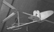
![[download nellie.gif (23K)]](http://www.w-p.dds.nl/bookaut/nellie.gif) |
Little Nellie parked safely |
Blade Element Theory
![[download topbld1.gif (2K)]](http://www.w-p.dds.nl/bookaut/topbld1.gif) |
top view of an autogyro |
Vertical descent
- All local angles of attack are small
- The type of flight is stationary: the rotor rpm, the airspeed, etc. do
not change
- The rotor carries all the aerodynamical loads
- The effects of blade flapping can be neglected
![[download bladstr.gif (2K)]](http://www.w-p.dds.nl/bookaut/bladstr.gif) |
local airspeed at a blade element |
As you can see in the picture on the right, the local angle of attack can
be divided into an aerodynamical part (αa) and a
structural part. The structural part is called "blade pitch" and is the angle
between the rotor disc and the zero-lift direction of the blade. The
aerodynamical part covers the local airspeed and is given by:
 |
eq. 1 |
In this formula voo denotes the descent velocity, vi the induced velocity (the downwash of the blades) and Ω*r the local speed due to the rotation of the blade. However, we started by saying that all local angles of attack were small. We can therefore use the approximation:
 |
eq. 2 |
Together with the structural part (the blade pitch setting) the local angle of attack becomes:
 |
eq. 3 |
where it should be noted that the pitch is the angle between the blade
orientation as it is and the blade orientation which gives no lift when the
aircraft is standing on the ground with a turning rotor. The local airspeed
can be given by:
|
|
eq. 4 |
As the angles of attack are small, this can be well approximated by:
|
|
eq. 5 |
These two quantities (airspeed and angle of attack) determine the local situation at each radial position in the rotor. Lift and drag of the airfoil section can now be calculated and combined into a "pulling force" and a "driving force". The driving force is defined as the total of all forces that spin up your rotor or slow it down. If the rotor is getting more spin, the driving force is positive. In the present situation (stationary vertical autorotation) the driving force is zero, because the rotor rpm remains constant. The local lift per radial unit of length is given by:
 |
eq. 6 |
In which c is the blade chord and the greek letter ρ is the air density. clloc is a coefficient that is only dependent on the shape and the angle of attack of the blade. We will assume that the blade chord is constant over the length of the blades. For regular airfoils and small angles of attack the coefficient of lift can be approximated by:
|
|
eq. 7 |
This really is all there is to the local lift (per radial unit of length) in our approximation. We can now give the full formula:
 |
eq. 8 |
The local drag per radial unit of lenth is given by a similar formula to the
one that gave the lift:
 |
eq. 9 |
In which cdloc is
again a coefficient that depends on airfoil shape and angle of attack only.
Fortunately, at very low angles of attack this coefficient doesn't vary much
and can be replaced by a constant drag coefficient, which we will call cd.
The local drag formula now becomes:
 |
eq. 10 |
As stated before, lift and drag are local forces that do not tell us much about the whole rotor. We will therefore determine the force in the direction of the rotating axis (we will call this the pull of the rotor) and the moment about the rotor axis (the drive). These force and moment are (both per radial unit of length):
|
|
eq. 11 |
and
|
|
eq. 12 |
|
from lift and drag to pull and drive |
![[Download blpnd.gif (2.4K)]](http://www.w-p.dds.nl/bookaut/blpnd.gif)
(see figure) We must be consistent in our approximations and we will therefore write:
|
|
eq. 13 |
and
|
|
eq. 14 |
The above formula shows that it is the blade lift that drives the rotor and the blade drag that slows it down. In a steady vertical autorotation the total drive of a blade equals zero. The total blade drive can be found by integrating over the blade, from the hub to the effective radius Re. This effective blade radius is generally taken to be 97% of the real blade radius. For the case of vertical autorotation it is not necessary to average over one rotation, because at all blade positions the aerodynamical situation is similar.
 |
eq. 15 |
Let's work this out:
 |
eq. 16 |
or:
 |
eq. 17 |
we can perform the integration to get the equation:
 |
eq. 18 |
We can solve for the difference between the descent speed and the induced speed at the rotor disc:
 |
eq. 19 |
To make this a positive value, only the positive root is of any value to us. We can therefore write:
 |
eq. 20 |
We will leave this result for a while and go back to the "pull"-formula. As αa is small compareed to unity and the local drag is small compared to the local lift, the second term in equation 13 can be neglected with respect to the first term. The local pull then simply becomes:
|
|
eq. 21 |
If the number of rotor blades equals N, the total rotor force in the direction of the rotor axis is:
|
|
eq. 22 |
Again, we can work this out:
 |
eq. 23 |
and perform the integration:
 |
eq. 24 |
Equation 20 can now be filled in to get the PULL formula:
 |
eq. 25 |
As you see, the pull formula depends on a lot of factors, among which are
the rotor tip speed Ω*R and
The rotor radius R. If
we could get these dependencies out of the formula, the rotor pulling force
would only depend on the shape of the rotor and not on its speed or size. This
way, model rotors (in windtunnels, for example) would produce the same results
as full-grown rotors of the same shape.
This is why so-called "coefficients" are so popular. Coefficients are
dimensionless quantities (just numbers without units) that describe a typical
situation. If you want to calculate your own situation you can easily
translate them to your own situation. We already have used coefficients for
lift and drag! For propellers and rotors the coefficient of Thrust (I called
it "PULL") is:
 |
eq. 26 |
If you know the CT,
just multiply instead of divide to get the Thrust. We can now insert equation
25 into equation 26 to calculate the CT.
If all works out well, CT should
only be dependent on the geometry of the rotor. Let's calculate CT and
group the factors a bit:
 |
eq. 27 |
Where we deliberately worked towards the so-called "solidity ratio", defined as:
 |
eq. 28 |
After some cleaning, we are left with:
 |
eq. 29 |
As you can see, the CT depends only on general numbers (Re/R is generally chosen to be 0.97, cd to be 0.012 and π is approximately 3.14) and rotor shape
Let us look at what we have got now. We can approximate the CT for a given rotor. In a steady vertical descent, the total PULL of the rotor is equal to the weight of the autogyro. Therefore, from a given weight and rotor, the rotational speed of the rotor can be calculated. This is the maximum obtainable rotor speed in a steady flight.
In the literature, CT is often defined otherwise, such that the flight speed replaces Ω*R. This also changes the value of CT. If you derive the PULL-formula for a forward flight, you will see that the PULL depends on both the flight speed and the rotor speed.
Possible Problems with an Autogyro
Ground Resonance
Description
![[Download gndres.gif (0.9K)]](http://www.w-p.dds.nl/bookaut/gndres.gif) |
Ground Resonance |
Pilot's solution
- Before flight: check if the blades are exactly opposing each other. Badly opposing blades do not give you ground resonance, but they will start the phenomenon if it is present.
- In general during take-off or landing: Remember that it is the rotor speed that amplifies the effect. So change the rotor speed as soon as possible (using the rotor brake or throttle).
Ground resonance was a problem during the first days of autogyros and helicopters, but it is now fully understood. If your autogyro suffers from this phenomenon at normal operating rotor speeds, something is definitely wrong with it!
Design solution
Pilot Induced Oscilation (or PIO)
Description
Pilot's solution
When you encounter this phenomenon during flight, the most difficult part is to recognise that you, the pilot, are an active part in it. Pilots always want to be in control (which is good!) and therefore automatically counteract all distubances. This is clearly the time you should not do that. It sounds very dangerous to let go of the controls during a growing banking oscilation, but it really is the solution! Your autogiro is a stable aircraft, so it will find a right flight path by itself.
Design solution
Power-pushover (or PPO)
Description
![[Download ppo.gif (1.3K)]](http://www.w-p.dds.nl/bookaut/ppo.gif) |
Power pushover |
Pilot's solution
- Avoid flying at zero-g! It is dangerous! You can get in a situation where you have little or no control over your aircraft. On top of that, you can encounter some serious mast-bumping, which can damage your rotor head.
- If you are in a PPO: reduce power immediately.
Design solution
- Take great care that the center of gravity of the whole aircraft remains somewhat above the line of thrust at all loading conditions. This is not as simple as it sounds! It means the designer (and the pilot) should know the vertical position of the center of gravity and should be able to adjust it (or to adjust the line of thrust).
- A horizontal stabiliser only helps at high speeds. As the phenomenon is largely speed-independent (the drag forces are small with respect to the thrust), mounting a large horizontal stabiliser does not overcome the problem for moderate or low speeds. Horizontal stabilisers should only be mounted to correct the aerodynamically unstable shape of the fuselage.
Unwanted Low Speed Yaw
Description
Pilot's solution
Design solution
Mast bumping
Description
Pilot's solution
Design solution
- Give the blades enough room to perform their normal movements.
- Choose the disc loading high enough.
- If all else fails: try using tip weights.
"Flying behind the power curve"
Description
![[Download powcur.gif (2.9K)]](http://www.w-p.dds.nl/bookaut/powcur.gif) |
the power curve |
Well, here it is: the power curve. There are two lines in the power curve:
- The line of the available power (continuous line) and
- the line of the required power (dashed line).
This chart is drawn only for stationary
horizontal flight, which means that the pilot keeps on flying at the
same altitude with the same speed. The chart shows that both the power
available from the engine and the power required to overcome the drag increase
with increasing airspeed. Yes, the engine becomes more effective when flying
faster! Sadly, the power required to fly at higher speeds increases more
rapidly, due to the increase in drag.
At the maximum speed, the two lines intersect and it is clear that the engine
cannot develop enough power to go any faster.
But what happens at minimum speed? To maintain a slower speed at a given
altitude, the pilot has to reduce the power and increase the angle of attack
(pull back the stick). At very low speeds, the angle of attack of the rotor
becomes so large that it is mainly giving drag instead of lift. In fact, the
engine is taking over quite a portion of total lift of the aircraft. This also
means that the pilot is unloading the rotor, which is really unwise. Unloading
the rotor will reduce he rotor speed. If the pilot could go to zero airspeed,
you would see an autogyro standing on it's tail, without the rotor turning!
Did I say autogyro? It is a helicopter by now! Obviously, the pilot can't get
that far.
At speeds that are less then the minimum speed, it is impossible to maintain
both speed and altitude. At the point of minimum speed itself, the pilot is
flying with full throttle, just as if he were flying at maximum speed! The
region of speeds that are less then the minimum speed is called "behind the
power curve". Flying behind the power curve is a phenomenon that does not only
occur with autogyros; some fixed-wing aircraft have it as well. However, the
minimum speed for fixed-wing aircraft often nearly coincides with the stall
speed. As autogyros simply do not stall, the phenomenon is better known with
autogyros.
Pilot's solution
Push the stick forward to gain speed. It will make you loose altitude, but you will loose altitude anyway. As you are probably already flying full throttle, your engine power can't help you anymore at this speed. (Some fixed-wing airliners have automatic "stick-pushers" to prevent the pilot from flying behind the power curve.)
Design solution
Tips for designing an autogyro
![[download wa120.gif (20K)]](http://www.w-p.dds.nl/bookaut/wa120.gif) |
The Wallis WA-120 |
Most of the tips below have been written down during the Wallis Days '98 and were told by Ken Wallis during a visit to his collection of autogyros.
- Don't make the fuselage too stable for banking. Both stable and instable fuselages are sensitive to gusts. The ideal fuselage is just stable with respect to it's angle of attack. The stability of the fuselage can be tested with a simple scale model.
- Mount the horizontal tailplanes in the slipstream of your propeller. It makes them more effective. The effectiveness increases with an amount of Δvp/v, in which v is the flying speed and Δvp is the increase in airspeed over the tailplanes due to the propeller.
- Beware that a pusher propeller is both carnivorous and coming in your
direction when you start your engine. If you use an electric starter, you
are safe in your autogyro. But an electric starter is heavy and if it fails,
you will still have to start your engine by hand.
If you start your propeller by hand, it is nice to have one hand on the airframe. When the thrust is more than expected, you can push the autogyro back with that same hand. A "dead-man" switch (a switch that only makes contact as long as you are pushing it down) mounted on the place where you should hold the pushing hand will allow you to shut down your engine if something is really wrong with it. When the engine is running fine you can use the real on-switch and let go of the dead-man switch.
- Apart from using a freewheel on the rotor drive, use a "spring back"
rotor clutch handle that disengages when you open the throttle.
- A "Fixed-wing" type of throttle is more in conformation with its use
than a "helicopter" type. Some fixed-wing aircraft use a so-called
"safety-throttle". This is a throttle that tends to go to full gas instead
of going to idle when the rod or cable breaks. In flight, this is safer,
because in case of a broken cable or rod you do not need to make an
emergency landing. Landing and maintaining height is done by switching the
engine on and off in such a situation. This construction will surely not
improve safety when doing a hand-start.
- A small ball-compass is about the lightest compass you can use.
- If you are doing night flights: light the
wool
thuft!
[sic, ????}
- Cross cables on parts that suffer from severe vibration.
- A high and narrow windscreen does not take away to much of the view if
it is wet.
- force the stick to steer to the side of the advancing blade during
spin-up. Both the engine and the rotor give a torque during spin-up.
- Use a rotor tachometer.
- Two trim handles are sufficient: one for each control rod. If you mount then next to each other, they can be operated in one movement.
- during engine start and rotor pre-rotation, the stick can be locked in the foremost position.
- use (parking-) brakes on all wheels.
- design the undercarriage in such a way that you will not be tackled when hand-starting the engine.
- When the autogyro has an enclosed cockpit, make it clear whether the rudder is controlled by pedals or by a bar. A bar is used more often, and is therefore what people expect.
- Make the undercarriage steer the same way as the rudder. It is unnatural, but als even Sikorsky did not have the heart to change the direction of the rudder control.
- It is nice to have the center of gravity of the whole aircraft close to the main wheels. This could mean that the nose wheel does not touch the ground when the pilot is not on board. This is not a problem and in fact quite common.
- use teeter stops to avoid "sailing" of the blades during low rotor rpm.
- Have the rotor torque work against the
engine torque during take-off.
- If you want to spin up the rotor by hand, There is a preferred direction of rotation: right blade forward, unless you are designing the aircraft for left-handed pilots.
- If a blade strut counteracts the rotation of the rotor, mark it with "Fit first, remove last".
Model autogyros are even less common than full size autogyros. Most model autogyros have a tractor engine, and someone has told me that it is hard to build a stable pusher-type model autogyro.
Rotor Stability
But in model autogyros, the pilot controls the position of the stick, and has no feeling of the aerodynamic forces. Also, the control servos are stiff: they clamp the rotor into a fixed position.
As we saw in the section about autogyro stability, the free rotor movement plays a part in the stability. So we must "unclamp" the rotor in a model autogyro. For instance, by using springs in the control rods.
Myths about the Autogyro
This chapter is meant to get rid of a few myths about the autogyro.
 |
Myth: You need more lift in order to climb
 |
| In climb, the carrying force is shifted from the rotor to the engine. |
As a result, the rotor will loose rotational speed.
Myth: Autogyros are safer or unsafer than other aircraft
![[download magni.gif (15K)]](http://www.w-p.dds.nl/bookaut/magni.gif) |
Isn't it cute? |
Both stories exist. People who never saw an autogyro fly often think it is
an aircraft that has come from a Disney movie. And obviously things from
Disney movies can't really fly. But autogyros are not created by a cartoon
artist and deserve to be taken more seriously. The fact that you haven't seen
something before does not mean that it is dangerous.
Autogyros are also not safer than other aircraft, because there just isn't a
fair comparison. In some ways it is safer, in some ways it is not. It is still
an aircraft and if something goes wrong, it is a long way down. Please do not
forget that autogyros form a separate class of aircraft with their own
technical characteristics and behaviour. Alas there are stories of people who
thought that they could fly an autogyro because they had either a fixed-wing
or a helicopter licence. NowTHAT is
dangerous.
Do not be scared by the strict safety rules in aviation. Pilots generally do
take safety very serious, and for a good reason: humans cannot fly. We are
mentally and physically not created for flying. So we will have to live with
flying machines and always be aware of the risks. That is the only way to keep
aviation safe.
Myth: Autogyro theory is the same as helicopter theory
Let me put it clear: an autogyro is a completely different kind of machine. In theory one can build an autogyro around any helicopter rotor (not the other way around), but that does not imply that the machines are equal. An autogyro rotor is a special kind of wing. The lifting force is powered by the airstream that the rotor is in. That is why an autogyro needs a separate installation to develop thrust. A helicopter rotor is a special kind of propeller. The lifting force is powered by the engine and a helicopter does therefore not need to be in an airstream.
This really is a huge difference. An autogyro is a lift-generating aircraft, while a helicopter is a tilted-thrust aircraft. To understand an autogyro, you must first understand the "wing properties" of the rotor. You should be able to draw a polar curve. You should know how lift and drag connect. Only after you have found out how much drag comes with the desired amount of lift, you would know how much thrust is needed. Thrust to overcome drag, not to produce lift. To understand a helicopter, you must first understand the "propeller properties" of the rotor. you should know how much power is needed to generate the desired rotor thrust. Only after you have found out how much rotor torque is generated, you would know how much power is needed for the tail rotor. Helicopters do not produce lift unless they are flying in autorotation.
Naturally, this is reflected in the theory. Helicopter theory is mainly about calculating powers and about the instability that comes with the rotor. Autogyro theory is mainly about calculating the aerodynamic forces and about the stability effects that come with the combination of the rotor and the engine.