Balloon Kite 2
Open-AWE_IP-Cloud
Gordon Spilkin 3/8/2017
Open-AWE_IP-Cloud
Gordon Spilkin 3/8/2017
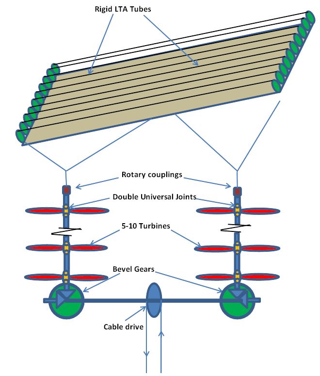
Since my original proposal I have decided that launching individual systems is complicated and time consuming. If all the kites are ganged together, then the system becomes much more stable and the whole ganged system can be launched at one time. This is especially true if all the kite units are made more rigid and neutrally buoyant or slightly lighter than air. As before, power will be obtained from multiple small turbines on common axes which will also serve as the tether. The power will be transferred to the ground by means of a single cable drive/tether. I originally favored two cable drives to stabilize the system, but with ganged kite units, stability is not a problem. I still favor two sets of turbines for each kite, to neutralize torque, balance the system and increase the number of available turbines.
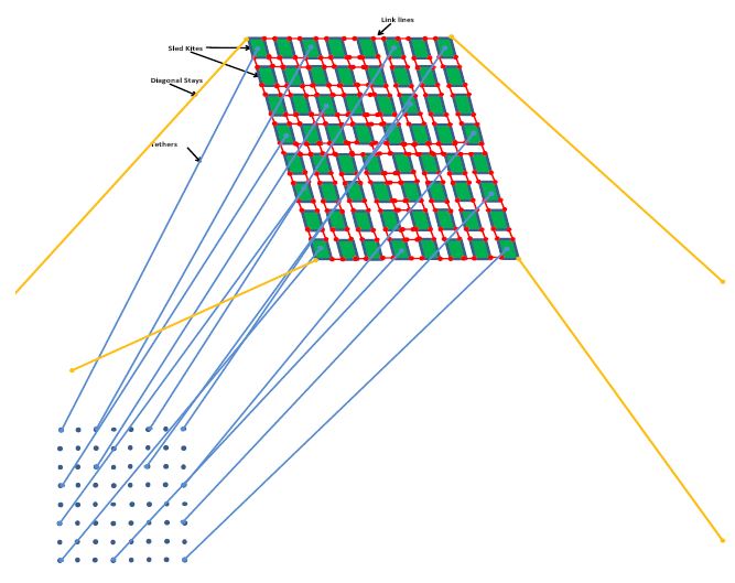
Here are some actual numbers of the system I propose: Each kite is 3 x 5 m sled kite with 5 m linking lines to the neighboring kites. The total area of these kites in a 10 by 10 grid would be 7125 sq. met. If each of the 100 kites produces 10 KW at rated wind speed then this system has a nominal rating of 1 MW. This system can take advantage of more wind at altitude since the whole canopy can be sloped so that downwind kites see fresh air and are not affected by turbulence from the upwind kites. The kites are prevented from bumping into each other by securing the whole canopy with diagonal stays.
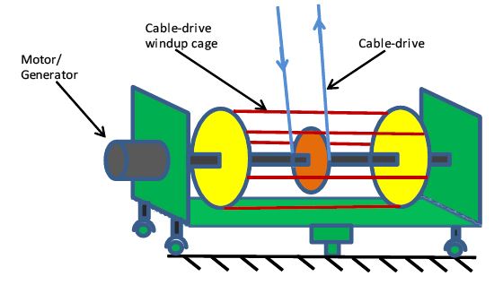
Here are some numbers I have calculated for my proposed system. At a wind velocity of 13.4 met/sec, a 3x5 m sled kite will have a lifting force of 284 Kg. In order to transmit 10 KW of power we require a differential force of 136 Kg in the cable drive. This differential force would be for 0.25 m diameter pulleys rotating at 600 rpm. The cable speed would be 7.85 m/ sec. This means that the tension on the high side is 210 Kg and 74 Kg on the slack side.
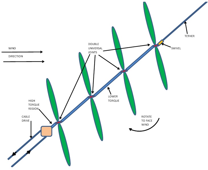
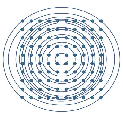
If we have a train of 5 - 10 turbines linked together with torsion tubes or tensegrity elements which are part of the tether, then all the turbines will turn at the same rate. Since the tether is at approximately 45 deg. to the wind direction, we can improve the efficiency of the turbines if they can orient to face the wind. This can be achieved by placing double universal joints at each turbine. Each turbine will naturally try to orient to face the wind. This will be countered by the tether tension which tends to align the axis of the turbine to the tether. I am not sure which factor predominates, but orientation to the wind is enhanced if the ratio of the length of the torsion tube to the length of the universal joint is increased. Based on the cosine cubed law, a substantial increase in efficiency will be obtained even with a small orientation to the wind.
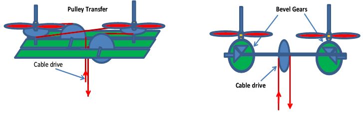
I can think of two options for transferring the torque of the turbines to the cable drive. One is a system where the two trains are linked together with auxiliary pulleys. This system requires a framework which may be heavy and obstruct the airflow to the bottom turbines. The second system uses bevel gears to transfer the power. In this mode the joining shaft must be designed to take the full load of the system. In both systems we have the option to increase the cable drive speed by varying the ratio of the bevel gears or the size of the pulleys.
Open-AWE_IP-Cloud
Gordon Spilkin 3/8/2017
Gordon Spilkin 3/8/2017