Multi-r Form-Finding Notes
Dynamic Form- radical morphing and topological surgery evolving on a tensile skeleton of persistent form. We can design a skeleton that supports evolutionary engineering of its supported parts.
Economy of Scope- variability of form and diversity of function. No single dead-end design down-select.
Dispatchability- responsiveness to season, peak demand, emergency disruptions of grid supply, etc.
Bulk Modes v. Local Modes- bulk laminar v. local turbulent wind harvesting regimes. Local modes harvest energy that stall bulk modes. An ideal design will do both bulk and local mode harvesting.
Many Wing System Validations- grid fins, starling murmuration, feathers, leaves, cellular/multi kites, etc.; all prove multi-wing lattices do bulk modes effectively.
Echinoderm Biomimetic Form Model- better than we alone could imagine. Note metamaterial edge-mode optimization: https://www.georgehart.com/sculpture/sand-dollars.html
[Ed adds: https://tinyurl.com/MandalasAWEformfinding ]
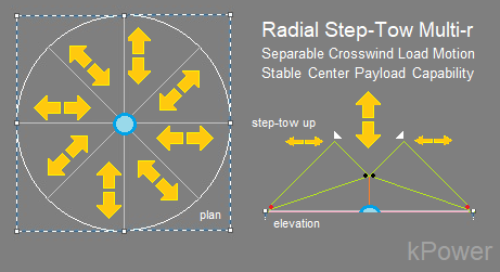
Radial Step-Tow Multi-r
Inspired by Jellyfish Locomotion Dynamics:

=============================

Max Langbein notes:
Even if that fractal concept still had a low power-per-area-ratio, would you still think it would be worth working out ?
(modeling,
doing simulations, first extremely simplified string mechanics only
using the movement modes and extremely simplified areodynamic
replacement models, then adding aerodynamics, then building a small
physical down-scaled model, iterating )
I see the movement modes already being worked on by joe.
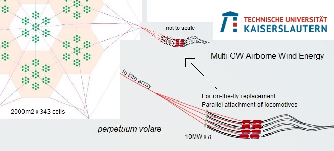
Even a >100MW installation over hambach mine would be impressive, and could be re-powered afterwards.
Of
course using a grid with self-organized motion modes, and power
transferred by self-stimulated mechanical waves running through the
grid instead of controlled movements, it would be more generic and less
control-intense, by that maybe also more robust.
Should I generally include tassos in the conversation ? Maybe a more terse introduction into the topic would be better instead.
============
====
=====
Max notes:
Hello, Thassos,
Thank you for sharing your thesis, containing deep thoughts about how to distribute forces, and algorithms to fill a structure in a way that maintains stability.
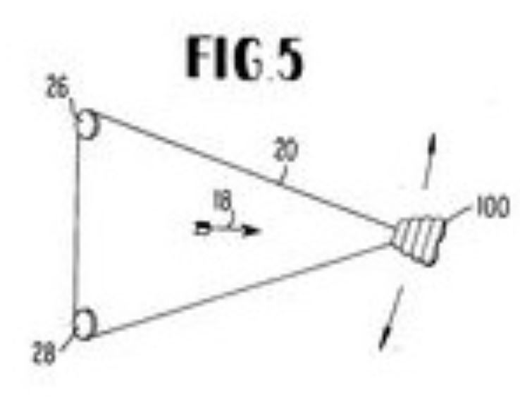
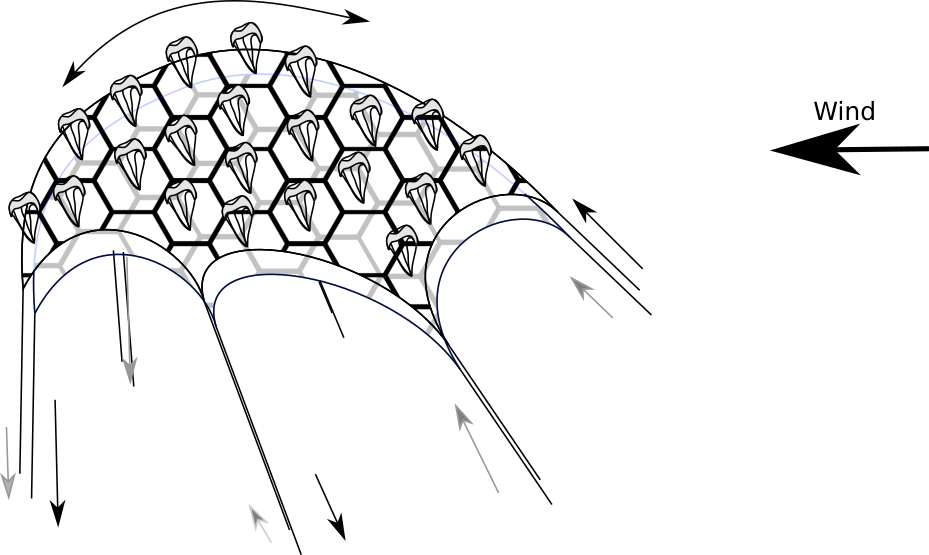
Our specific problem here in Airborne wind energy, or our idea for a large airborne wind energy structure, would be a large dome-like structure,which is kept tensioned and upright by many little softkites. In the starting mode, the dome is moved by winches in a step tow fashion (each of the six pulley doing a sinus ,each pase-shifted by 60 degrees).afterwords, the kites move the winches still in the same fashion however with different force distributions.
The
dome would be two-layered to make it possible to steer the kites
angles slightly (needed to switch between power gen modes)
The challenge here is that the dome does not keep it's shape, but is layed flat initially, then slightly arched, etc., but still all strings should be kept tensioned.
One
solution would be a strongly hierarchical structure, however that has
the disadvantages that it has only a low density, and is not very
flat, by that preventing "layering" of the domes which would be a nice
re-powering possibility of a site (just add more kite layers)
The honeycomb structure in the images inserted here is just for illustration, also the kites on the dome are only illustration.
Maybe you could come up with a structure for that.
In the kites we still discuss if simple sails kept in shape and position by the structure, or self-adjusting kites with maintain aoa to be lifted, would be better.
I
Tassos responds:
Dear Max,
Max notes:
...
Dear Max,Thank you for your email. It's a pleasure to meet you....The approach to AWE you describe certainly sounds very interesting. With regards to the double-layered dome you are referring to, it reminded me of some experiments I had done during my MSc. In fact, it was a project that preceded my thesis (that you mentioned), but it was based on the same principles, i.e. particle-spring simulation algorithms. However, in that case, I investigated certain fixed topologies (or uniform connectivity patterns) of nodes arranged on a 2D grid (whereas in the thesis the topology generation was the point of focus). In the few cases of more dense connectivity patterns I had tested, the nodes would fall into a 3D 2-layered (or 3-layered) space frame structure on their own in order to achieve equilibrium. I had actually made a short video of this project at that time that may perhaps help illustrate what I am trying to describe. I just managed to find it and uploaded it in the following link:
Nice user-friendly application. Impressive.
I suppose that the overall isomorphic hexagonal shape of the structure you are investigating (shown in the images you sent) is to accommodate the 6 points of support and associated winches along with the phase difference in motion. I think that other, perhaps even more complex forms could also be feasible, although simplifications may be required to accommodate the dynamic motion (and possibly other complex) aspects, at least as a starting point.
The
inner structure is not fixed being hexagonal, the only constraint is
that the cell centers of the upper layer being near nodes of the lower
layer. (the kites being thought of residing in the cells of the upper layer and steered by the nodes of the lower)
Initially
I looked at a tri-winch setup (being the simplest setup allowing
movements in all directions) , however then the area that could be kept
tensioned was a bit small.
If I understand correctly, you want the structure to maintain a certain (controlled?) degree of flexibility and allow deformations, while maintaining tension in all connections. Provisionally, I would think that this could be achievable through the configuration of the connectivity pattern (topology) and the possible combination of rigid and tensile elements, but granted the complex nature of the structure's resulting motion due to wind and mechanisms (winches), it may not be a straightforward task.
Maybe a simplified sim of the kite aredynamics has to be combined with the network sim and tested to find a good structure.
In any case, I think that particle-spring algorithms could be a suitable tool for form-finding and simulating such a structure.
Maybe
the links/springs would have to be more elaborated, using some simple
analytical model of the actually used material of the tethers,
including drag.
After all, tether drag is a non-negligible property of an AWE system.
Dave Santos responds:

